What Is Power over Ethernet and How to Add PoE to Your Network?

saki shao

With the wide application of VoIP phones, IP cameras, and wireless access points, Power over Ethernet (PoE) has made great strides in recent years. And PoE network is expected to expand rapidly in the future due to the increasing number of IoT applications and smart device deployments and newly ratified standards designed to support more smart devices. In this article, we will provide an introduction covering various aspects of PoE such as PoE wiki, PoE standards, PoE types, PoE classes, and PoE applications.

What Is Power over Ethernet (PoE)?

PoE is a networking technology that can transmit both data and power over one single standard Ethernet cable. It allows us to use network cables such as Cat5/Cat5e/Cat6/Cat6a cables to provide data connections and electric power to wireless access points, IP cameras, VoIP phones, PoE lighting and other powered devices (PDs). With the use of PoE technology, we can easily deliver power to indoor or outdoor PDs without the need to install additional electrical infrastructure or to deploy power outlets at every endpoint.


Benefits of PoE Network—Why Use Power over Ethernet?

Besides the above-mentioned benefits, there are several more appealing reasons for adopting PoE in networking.

Time & Cost Saving: By using PoE in the network, we do not need to deploy electrical wiring and outlets for terminal PDs. This will help to save much power cabling cost especially when there are lots of PDs in the network. Furthermore, there is no need to hire a qualified electrician for the PoE network, so you may also save both time and money on electrical installations.

Flexibility: Since Ethernet network cables are easier to deploy than electrical ones, PoE networking allows us to install PDs nearly anywhere rather than near the electrical outlets. This offers a ton of flexibility for setting up and repositioning terminal devices.

Reliability: PoE power comes from a central and universally compatible source rather than a collection of distributed wall adapters. It can be backed up by an uninterruptible power supply (UPS) or controlled to easily disable or reset devices. By doing so, the PDs will run as usual even though Power Sourcing Equipment (PSE) breaks down.

Evolutionary Path of the Power over Ethernet (PoE)

Institute of Electrical and Electronics Engineers (IEEE), Cisco, and the HDBaseT Alliance have released several standards to define PoE. These standards include IEEE 802.3af, IEEE 802.3at, IEEE 802.3bt, Cisco UPOE, and Power over HDBaseT (PoH).

Evolutionary Path of the Power over Ethernet (PoE)

PoE Types

Due to different classification standards, PoE can be divided into different types. Currently, there are 4 PoE types based on IEEE PoE Standard: Type 1(IEEE 802.3af), Type 2(IEEE 802.3at), Type 3(IEEE 802.3bt), and Type 4(IEEE 802.3bt), as shown in the following chart.

PoE Types

PoE vs. PoE+ vs. PoE++ (UPoE )vs. PoH

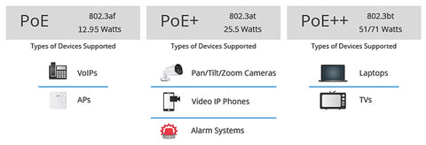
PoE (IEEE 802.3af), also known as PoE type 1, provides up to 15.4 watts of power per port and is used for devices like IP phones and cameras. PoE+ (IEEE 802.3at), PoE type 2, offers up to 30 watts and powers devices like PTZ cameras. PoE++ or UPoE (IEEE 802.3bt), also referred to as PoE type 3, delivers up to 60 watts and 100 watts, PoE type 4, per port for high-performance devices. Power over HDBaseT (PoH) enables power and data transmission for AV equipment over a single cable. The figure below illustrates the common applications of different PoE types for your reference.

PoE vs. PoE+ vs. PoE++ (UPoE )vs. PoH

PoE Classes

Power over Ethernet (PoE) classes define standardized power levels for different network devices. These classes ensure compatibility between Power Sourcing Equipment (PSE) and Powered Devices (PD).

The classes, ranging from Class 1 to Class 8 as the above chart shows, correspond to specific IEEE standards, indicating the maximum power output of the PSE and the maximum power input of the PD. Let’s delve into more details about each class:

PoE Classes

Class 1 is suitable for low-power devices such as IP phones, voice-over-IP (VoIP) devices, and basic sensors.

Class 2 is intended for devices that require slightly higher power, including wireless access points, small IP cameras, and IP intercom systems.

Class 3 is commonly used for devices that require moderate power, such as larger IP cameras, point-of-sale systems, and access control devices.

Class 4 provides increased power delivery capabilities and is suitable for power-hungry devices like pan-tilt-zoom (PTZ) cameras, video phones, and thin clients.

Class 5 introduces the support for four pairs of Ethernet wires, enabling higher power transmission. It is designed for devices with more demanding power requirements, including advanced PTZ cameras, multi-channel wireless access points, and small LED lighting systems.

Class 6 provides increased power delivery capabilities beyond the previous classes. It can support devices like high-power pan-tilt-zoom cameras, multi-radio wireless access points, and small LCD displays.

Class 7 offers even higher power capabilities introduced with the IEEE 802.3bt standard. It is suitable for devices like high-performance access points, large displays, and thin clients requiring substantial power.

Class 8 represents the highest power class defined by current PoE standards. It is designed for power-hungry devices such as video conferencing systems, advanced lighting systems, and digital signage

It’s important to note that the power levels specified for each class represent the maximum allowable values, and the actual power delivered or consumed by the PD may vary based on its specific power requirements and negotiation with the PSE. Besides, understanding PoE classes allows network administrators to ensure that the power requirements of their devices align with the capabilities of their PoE infrastructure, ensuring proper operation and avoiding potential power supply issues.

Passive PoE vs. Active PoE

Power over Ethernet can also be divided into passive PoE and active PoE in general. Active PoE is the standard PoE which refers to any type of PoE that negotiates the proper voltage between the PSE and the PD device. Passive PoE is a non-standard PoE technology. It can also deliver power over the Ethernet line but without the negotiation process.

How to Add PoE to Your Network?

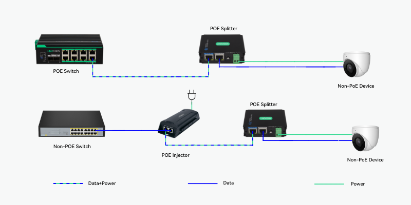
The PoE supplied in the network generally comes from three different sources: PoE switch, PoE injector, and PoE splitter. The PoE switch is the easiest way to power up the PDs. You only need to run Ethernet cables from a PoE network switch port to the terminal PoE device. A PoE injector is used when there is no PoE switch in the network. It has an external power supply and is responsible to add power to data that is coming from a network switch that is not PoE-capable. PoE splitters also supply power, but they do so by splitting the power from the data and feeding it to a separate input that a non-PoE-compliant device can use. It is commonly used for deploying remote non-PoE devices with no nearby AC outlets in the network.


Common FAQs on PoE Network

Q: What is the voltage of Power over Ethernet?

A: Power over Ethernet is injected onto the Ethernet cable at a voltage between 44v and 57v DC, and typically 48v is used. This relatively high voltage allows efficient power transfer along the cable, while still being low enough to be regarded as safe.

Q: What data speed does PoE offer?

A: Generally, PoE can deliver data rates at 10/100/1000Mbps over Cat5, Cat5e and Cat6 cables. Now thanks to the widespread IEEE 802.3bt PoE standard and PoE++ technology, PoE is able to deliver speeds of 2.5 Gbps to 5 Gbps over 100m and reaches 10 Gbps in recent times.

Q: Are there any limitations of PoE network?

A: Yes, PoE network does have some pesky limitations. First, it has a restricted reach of 328 feet (100 meters) which limits the viable locations where users can operate a remote IP-enabled device. Second, a single PSE such as a PoE switch usually connects to multiple PDs. If the PSE broke down, all the PDs will stop working. Therefore, it is important to buy qualified switches from a reliable supplier. In addition, you may also consider connecting the PSE to an uninterruptible power supply system.

Q: What are PoE midspan and PoE endspan?

A: The PoE midspan is usually a PoE injector that serves as an intermediary device between a non-PoE switch and the terminal PoE-capable powered device. A PoE endspan, which is commonly called the PoE network switch, directly connects and supplies both PoE power and data to a PD. PoE endspan provides power over the data pairs, also known as PoE Mode A. PoE midspan provides power using the pins 4-5 and 7-8, also known as PoE Mode B.

Read more →

PoE Switch vs PoE Injector: Why Choose PoE Switch to Build Wireless Networks?

saki shao

Power over Ethernet (PoE) technology has transformed the way we construct wireless networks by enabling the simultaneous transmission of data and power over a single Ethernet cable. This innovative approach eliminates the need for additional modifications to the existing Ethernet infrastructure, allowing power devices (PDs) like IP cameras and wireless access points to receive power seamlessly. To gain a comprehensive understanding of PoE networks, you can consult resources such as the Demystifying PoE Network: Features, Standards, Types, and Common FAQs guide. When implementing PoE technology, you have two primary options: PoE switches and PoE injectors. In this article, we will delve into the distinctions between these two alternatives and elucidate why a PoE switch is often the superior choice for constructing wireless networks.

What Is A PoE Switch?

A PoE switch is an Ethernet switch equipped with integrated PoE capabilities, enabling it to deliver power directly to connected devices through the Ethernet cable. This eliminates the need for additional equipment, as you can directly connect PoE-enabled devices like IP cameras and wireless access points to the PoE switch using Ethernet cables. The switch seamlessly provides power to the devices, simplifying the setup process and reducing the complexity of the network infrastructure.


What is A PoE Injector?

A PoE injector is a device designed to enable PoE functionality in non-PoE network switches or routers. It acts as an intermediary between the non-PoE switch and the PoE-enabled device. By connecting the injector between these two components, it injects power into the Ethernet cable, delivering power to the device. However, it's important to note that utilizing a PoE injector adds an extra step to the installation process. You need to connect the injector to both the PoE-enabled device and the non-PoE switch, ensuring that power is properly supplied to the device.

Build Wireless Networks: PoE Switch vs PoE Injector

While both PoE switches and PoE injectors have the capability to deliver power over Ethernet cables, there are compelling reasons why a PoE switch is frequently considered the superior option when it comes to constructing wireless networks.

PoE Switches Are More Convenient and Easier to Install

PoE switches offer greater convenience and simplicity compared to PoE injectors when it comes to installation. Unlike PoE injectors, PoE switches eliminate the need for additional equipment, streamlining the installation process and reducing cable clutter. With a PoE switch, powering your devices becomes effortless since the switch itself provides power, eliminating the need for a separate injector. On the other hand, utilizing a PoE injector necessitates an additional installation step, potentially consuming more time and requiring extra equipment.

PoE Switches Are More Cost-Effective

When taking a long-term perspective into account, PoE switches provide superior cost-effectiveness. Although the initial investment in a PoE switch may be higher compared to a PoE injector, the overall cost savings over time are significant. By eliminating the need for additional injectors, you avoid the expense of purchasing and maintaining multiple devices. Moreover, the streamlined installation process and centralized power management offered by PoE switches result in time and effort savings, further contributing to cost efficiency.

PoE Switches Offer Greater Flexibility and Scalability

PoE switches provide enhanced flexibility and scalability compared to PoE injectors. With a PoE switch, you have the capability to connect multiple PoE-enabled devices to a single switch, offering the flexibility to expand your network as required. This allows for efficient network management and reduces the need for additional infrastructure. In contrast, a PoE injector can only provide power to a single device, limiting the scalability of your network and potentially requiring the installation of multiple injectors for additional devices. The ability of PoE switches to accommodate multiple devices makes them a more versatile solution for network expansion.

PoE Switches Are More Efficient for Building Wireless Networks

Deploying a wireless network using PoE switches is a more efficient approach compared to PoE injectors. When constructing an enterprise PoE wireless network, the Power over Ethernet switch serves as a connection point between the router and the Internet. This network configuration establishes seamless network connectivity between PoE wireless network devices and computers that are wired to the switch. The PoE wireless access points are directly connected to the PoE switch, receiving both power and network connectivity. These access points facilitate the connection of multiple wireless devices to the network, effectively extending its coverage and capabilities.

The picture below shows a wireless network in an office. The wireless AP is installed on the ceiling. Cat5e or Cat6 network cable delivers data and power from the nearest PoE switch. Compared with the PoE injector, using a PoE Ethernet switch to power the AP is more efficient for the wireless network because you don't need to worry about the power outlets. In addition, you don't have to specifically buy a Cat5e or Cat6 Ethernet cable for power transmission.

Wireless Network in an Office

PoE Switches Offer Better Management and Control Features

PoE switches provide superior management and control capabilities compared to PoE injectors. They come in a wide range of options, catering to various applications, from simple unmanaged edge switches with a few ports to advanced rack-mounted units with extensive management features. With a PoE switch, you gain the ability to easily monitor and control the power usage of connected devices. This allows you to optimize the performance of your network and reduce energy costs by efficiently managing power allocation.

In contrast, PoE injectors lack these management and control features. They simply deliver power to PoE devices without offering the same level of monitoring and control functionality. Furthermore, PoE switches adhering to the IEEE 802.3af standard provide Gigabit speeds, ensuring both power and data transmission over a single cable. This eliminates the need for additional wiring, power sources, or adapters, streamlining the network setup process.

Endspan PoE Switch

How to Choose a PoE Switch for a Wireless Network?

When planning to choose a PoE switch, we recommend that you should take the following three aspects into consideration.

  • The number of ports of PoE switch, which can affect the number of powered devices that can be connected to a PoE switch.

  • The power budget and PoE Standard of a PoE switch are two important points that cannot be ignored, both have an impact on PoE switch's power consumption.

  • In terms of managed or unmanaged PoE switch, one thing is that when connecting with PoE devices like IP cameras, smart managed PoE switches can detect whether they are PoE-compatible and supply power automatically for the remote-powered devices.

For more detailed information about how to choose a PoE switch, you can click: PoE vs PoE+ vs PoE++ Switch: How to Choose? 

Conclusion

In conclusion, while both PoE switches and PoE injectors can provide power over Ethernet cables, a PoE switch is often the better choice for building wireless networks. PoE switches are more convenient, easier to install, efficient, offer greater flexibility and scalability, and provide better management and control features than PoE injectors. By choosing a PoE switch, you can build a more efficient and effective wireless network that meets your needs and helps you achieve your goals. PoE switch is available in Linovision, where you can find a wide selection of PoE switches. For detailed information and product availability, please visit our website at www.linovision.com or contact us.

Read more →

Troubleshooting Common PoE Errors and Solutions

saki shao

Introduction:


In a PoE power supply system, the essential components are the Power Sourcing Equipment (PSE), the Powered Device (PD), and the PoE cables. When issues arise with PoE, it often manifests as the PoE switch failing to provide power, resulting in the powered devices ceasing to function. These failures can stem from various factors, including hardware and software-related issues. This article aims to help you accurately identify the root causes of PoE errors and minimize troubleshooting time. We will discuss three common PoE faults and provide troubleshooting methods for Power over Ethernet.

PoE Error 1: PoE Switch Fails to Provide Power

One of the most frequently encountered PoE errors is when a PoE-powered device (PD) fails to boot up due to issues with PoE components or incorrect configuration commands. Follow the steps below to address this problem:

Step 1: Verify PoE IEEE Standards and Power Modes of PSE and PD

Ensure that both the Power Sourcing Equipment (PSE) and PD comply with PoE IEEE standards. It's important to note that non-standard PoE switches, also known as passive PoE switches, deliver power over Ethernet lines at a fixed voltage, regardless of whether the terminal device supports PoE or not. Improperly prepared passive PoE switches may damage the terminal devices. Additionally, the power modes of PSE and PD can contribute to PoE faults. There are three PoE modes: Alternative A, Alternative B, and 4-pair delivery. If a PD supports only PoE mode B power delivery while the PoE switch is based on Alternative A, they will not work together. Confirm the power supply modes of PSE and PD with the vendor.

Step 2: Check the PoE Cabling

Mismatched Ethernet cables and PoE ports can result in network failures. Furthermore, PoE failures can occur if the cable has hardware faults or fails to meet necessary standards. Therefore, it's highly recommended to ensure that the Ethernet cable supports PoE and is functioning properly before connecting the powered device.

Step 3: Verify Sufficient PoE Power

In theory, the PSE device interface can automatically detect the connected PD. If the power supply is insufficient, the PD will not receive power. Make sure that the power required to run the PDs does not exceed the power budget of the PoE network switch. If a PSE detects that the PD's power class falls within its capacity, it will power on the PD.

Step 4: Check PoE Power Management Configuration

Verify whether the switch interface has automatic PoE power management configuration enabled. If not, you will need to manually deliver PoE power to the connected PDs through the PoE network switch interfaces.

PoE Error 2:  Intermittent Power Loss or Reloads of a PoE PD

What if a functioning PD experiences intermittent power loss or reloads? These situations may arise due to insufficient power supply and poor-quality PoE cables.

Step 1: Check Whether PoE Power Is Sufficient

A PD can power off or reload intermittently if the PSE's output power is insufficient to support all PDs operating at full power consumption. This can cause the PoE switch to fail to provide power. Take IP cameras as an example. During testing of extended functions such as Pan-Tilt-Zoom, heaters, or wipers, the PD may consume significantly more power than during normal operation. If no additional power is available, the camera may get stuck in a continuous boot cycle. To troubleshoot this PoE fault, measure the power requirements of the IP camera during startup and use an appropriate PSE to provide sufficient power.

Step 2: Check the PoE Cabling

If the Ethernet cable used in a PoE link is over 100 meters or has power loss due to the material and resistance of the cable itself, the PD would not get sufficient power, causing issues like network failure or latency. If the cables are not qualified, it will lead to PoE faults as well.

PoE Error 3: Inconsistent Powering of PDs on the Same PSE

If some PDs are receiving power while others connected to the same PSE are not, follow the tips below:

Step 1: Check if PDs Are Available on Other Ports

Determine whether the issue lies with specific ports on the PSE. Disconnect the PoE cable between the Ethernet switch port and the non-powered PDs. If the PDs receive power when connected to other PoE ports, it indicates a problem with specific ports. Verify if the port is shut down or error-disabled using configuration commands. If so, enable PoE functions through the appropriate command.

Step 2: Check the PoE Power

If newly added PDs to PSE ports are not powering on, it may indicate that the PoE switch's power budget is depleted. Ensure that the remaining PoE power in the PSE is equal to or greater than the maximum output required by the connected PDs. Additionally, limit the per-port current to safe levels and consider using additional PSE devices if necessary.

PoE Error 4: PoE Cameras Not Powered

If your camera cannot be powered on while using a PoE Switch or PoE injector, you may follow the tips below to solve your problems.

Step 1: Verify Camera Compatibility with PoE Switch/Injector

Check the compatibility requirements of your camera with the PoE switch or PoE injector. Ensure that the specifications of the PoE switch or injector align with the camera's requirements.

Step 2: Check if the Camera Is Fully Connected to the PoE Switch/PoE Injector

Inspect the PoE port lights on thePoE switch or PoE injector to confirm if the camera is fully connected. If the lights are not illuminated, try plugging the camera into other ports and using a different Ethernet cable. Also, check if the PoE port of the switch is damaged or rusty. You can test this by connecting the camera to other functioning PoE ports.

Step 3: Check if the PoE Module of the Camera Gets Power

If the camera's PoE module is not receiving power, use a DC adapter with the correct output voltage to power the camera. Make sure the DC/AC adapter is available and compatible. Typically, the adapter has an indicator light that indicates the presence of power. Some IP cameras support both DC and AC power supply ports, such as DC12V/2A and AC 24V/3A. Verify that the adapter's specifications match those of the camera.

Conclusion

The four errors mentioned above basically cover the problems that PoE switches are often prone to. If you meet other problems in the process of using PoE switches, you can contact Linovision IT experts for answers. Linovision not only provides you with cost-effective and excellent quality PoE switches but also provides a series of technical support services to ensure your after-sales worry-free.

Read more →

How to Connect Linovision LoRaWAN Gateway to HTTP(s) Server?

saki shao

Description

Linovision LoRaWAN gateways support sending data packets to third party MQTT/HTTP/HTTPS server. We can create a new application on gateway, which can define the method of decoding the data sent from LoRaWAN end-device and choosing HTTP(S) data transport protocol to send data to HTTP(s) server.


Requirement

  • Linovison LoRaWAN Gateway: IOT-G6x, IOT-G8x
  • HTTP/HTTPS Server


Configuration

Step1. Enable the gateway built-in network server.

Go to Packet Forwarder > General to enable the localhost server address.


Enable the Network server on Network Server > General page.


Step2. Add an Application and Profiles.

Go to Network Server > Applications to add a new application, then click save.

Name: user-defined, arbitrary value

Description: user-defined, arbitrary value

Payload Codec: None or custom your decoder


Go to Network Server>Profiles to add a new profile, then click save.

Name: user-defined, arbitrary value

Max TXPower: default value

Other parameters can be checked from LoRaWAN nodes user guides or you can keep all settings by default.


Step3. Add LoRaWAN nodes to the gateway.

Go to Network Server > Device, add a new device, click save&apply.

Device Name: user-defined, arbitrary value

Description: user-defined, arbitrary value

Device-Profile: choose one of corresponding profiles added before.

Application: choose one of corresponding applications added before.

Other values can be confirmed with the LoRaWAN node manufacturers.


When the status of it is “activated”, that’s mean above steps are done correctly.


Step4. Forward data to HTTP(s) server.

Go to Network Server > Applications to add a “data transmission” for the application.


Fill in the HTTP(s) URL information for each data type, click save.

Uplink data: the URL address to receive all uplink data.

Join notification: the URL address to receive join notification.

ACK notification: the URL address to receive all ACK notification.

Error notification: the URL address to receive all error notification.


Note: If there is user credentials when we access to HTTP(s) server, please add HTTP header, and fill in correct account and password.


If we get data packet on the corresponding URL of HTTP server like below, that’s mean we have connected with HTTP server successfully.


Note: The difference of forwarding data to HTTPS server is that you need upload related gateway certification on your HTTPS server (Contact Linovision to get certification).


FAQ

Q1. Why did the server not receive the data sent by the gateway?

A1: Go to Maintenance > Tools > Ping, confirm the gateway can ping to the HTTP address you filled in successfully like below, then check all of above values filled in are correct.


Q2. How to send decoded data packet to HTTP/HTTPS server?

A2: Refer to How to Use Payload Codec on Linovision Gateway.

Read more →

How to Remotely Control Devices via MQTT on Linovision Gateway

saki shao

Description

When working as embedded network server, Linovision LoRaWAN gateways support both sending data packets to third party MQTT/HTTP/HTTPS server or receiving the downlink commands to transfer to LoRaWAN end devices.


Requirement

  • Linovision LoRaWAN Gateway: IOT-G56, IOT-G63 V1, IOT-G65, IOT-G67, IOT-G8x (Firmware version 80.0.0.64 or later)
  • MQTT Server/Broker
  • MQTT Client tool: take MQTT Explorer as example


Configuration

Step1Connect gateway to MQTT broker.

Refer article How to Connect LoRaWAN Gateway to MQTT Broker?to connect gateway to MQTT broker and ensure the broker and MQTT client can receive uplinks from devices.


Step2Send Downlink Command from Gateway

Set the gateway to send downlink commands to device directly to check if the device can receive the downlink commands and take actions.

Device EUI: the device EUI to send downlink commands

Type: downlink command type. For Linovision devices, please select hex type.

Payload: downlink command content (get from device manufacturer). For Linovision devices, please refer to downlink command contents on corresponding user guides

Port: application port of device. It is 85 by default for Linovision devices.

Confirmed: after enabled, the device will send confirmed packet back to gateway if it receives the command. If not receive, the gateway will resend the downlink command 3 times at most.

Note: for class A type devices, the gateway will add the command to queue and send it when the class A device send uplinks.


Step3. Publish Topic on MQTT Explorer to send downlink data to device. 

Set a Downlink Data topic. If you need to send MQTT downlink to specific device, please add “$deveui” on the topic.

Example: /linovision/downlink/$deveui


Publish Topic Format :

/linovision/downlink/[devEUI]

Example :

From the gateway, we can get the device EUI about the device we want to control:


So we can publish a topic on the MQTT Explorer like below:

Topic: /linovision/downlink/24e124126a148401

Format: json

Content: 

send as below format and replace the data content as downlink command

{"confirmed": true, "fport": 85, "data": "CQEA/w=="}
JavaScript


After click Publish, we can go to Network Server > Packets to check. If the gateway have subscribe corresponding downlink topic data successfully, there will be at least one grayed message packet record.


Linovision Device Command Examples

The MQTT downlink command format is fixed as below:

{
"confirmed": true,       //Set as true or false
"fport": 85,            //application port of device
"data": "BwAA/w=="    //base64 format downlink command
}
JavaScript

For Linovision devices, click here to convert hex format command to base64 format. Here are Linovision controller common commands:

Model

Command

Command (Hex)

Command (base64)

IOT-C50x

Set GPIO1 low

Set GPIO1 high

Set GPIO2 low

Set GPIO2 high

030000ff

030100ff

040000ff

040100ff

AwAA/w==
AwEA/w==
BAAA/w==
BAEA/w==

IOT-C300

Set DO1 low

Set DO1 high

Set DO2 low

Set DO2 high

070000ff

070100ff

080000ff

080100ff

BwAA/w==
BwEA/w==
CAAA/w==
CAEA/w==

IOT-C11xx

Set DO1 low

Set DO1 high

Set DO2 low

Set DO2 high

090000ff

090100ff

0a0000ff

0a0100ff

CQAA/w==
CQEA/w==
CgAA/w==
CgEA/w==


----END---

Read more →

How to Connect LoRaWAN Gateway to MQTT Broker?

saki shao

Description

When working as embedded network server, Linovision LoRaWAN gateways support sending data packets to third party MQTT/HTTP/HTTPS server. We can create a new application on gateway, which can define the method of decoding the data sent from LoRaWAN end-device and choosing MQTT data transport protocol to send data to MQTT server.


Requirement

  •  LoRaWAN Gateway: IOT-G8x (Firmware version 80.0.0.64 or later), IOT-G65, IOT-G67, IOT-G56, IOT-G63 V1
  • MQTT Server/Broker
  • MQTT client tool: take MQTT Explorer as example


Configuration

Step1. Enable the gateway built-in network server.

Go to Packet Forwarder > General to enable the localhost server address.


Enable the Network server on Network Server > General page.


Step2. Add an Application

Go to Network Server>Applications to add a new application, click save.

Name: user-defined, arbitrary value

Description: user-defined, arbitrary value


Step3. Connect gateway to MQTT broker.

Go to Network Server > Applications to add a “data transmission” for the application. One application can add only one MQTT integration.


Fill in the MQTT broker information and create topic to store different data type, click save.

Broker Address: IP address/domain of MQTT broker

Broker Port: communication port of MQTT broker

Client ID: user-defined, a unique ID identity of the client to the server.

User Credentials and TLS should be enabled and configured as required.

Note: if MQTT broker is HiveMQ, please do enable TLS and set the option as CA signed server certificate.


After MQTT configuration complete, you can check connection status here:


Step4. Add LoRaWAN nodes to the gateway.

Go to Network Server>Profiles to add a new profile, then click save. You can also use pre-defined profiles.

Name: user-defined, arbitrary value

Max TXPower: default value

Other parameters can be checked from LoRaWAN nodes user guide or you can keep all settings by default.


Go to Network Server>Device to add a new device, click Save&Apply.

Device Name: user-defined, arbitrary value

Description: user-defined, arbitrary value

Device-Profile: choose one of corresponding profiles added before.

Application: choose one of corresponding applications added before.

Other parameters can be confirmed with the LoRaWAN node manufacturers.


When the status shows as below, that’s mean above steps are done correctly.


Step5. Add uplink data topic.

Customize the uplink data to publish to MQTT broker and save the settings. If you add “$deveui” on your topic, you can replace it as real device EUI when subscribing topics. 

Example: /linovision/uplink/$deveui


Step6. Subscribe topic from MQTT client to get uplinks.

MQTT explorer is a comprehensive MQTT client and it can be replaced to other kinds of MQTT client tools(MQTT.fx, MQTT Box, etc.)

Open the MQTT Explorer, and fill in related MQTT server information in the popup window.

Name: user-defined

Protocol: mqtt://

Host: MQTT broker address

Port: broker port

User name/Password: if there is user credentials, please fill in it. If not, keep them blank.


Click ADVANCED,copy the Uplink data topic on the gateway, and paste it on the MQTT explorer, click +ADD.


Keep MQTT client ID by default,then click BACK and click CONNECT.


After while, the data will be forwarded to MQTT broker and the MQTT Exploerer can receive the data from MQTT server.


The uplink format is fixed as json and the content is as below.


{
  "applicationID": 1,                   // application ID
  "applicationName": "cloud",           // application name
  "deviceName": "24e1641092176759",     // device name
  "devEUI": "24e1641092176759",         // device EUI
  "time": "2020-0327T12:39:05.547336Z", // uplink receive time
  "rxInfo": [                           // lorawan gateway information related to lora
    {
      "mac": "24e124fffef021be",        // ID of the receiving gateway
      "rssi": -57,                      // signal strength (dBm)
      "loRaSNR": 10,                    // signal to noise ratio
      "name": "local_gateway",          // name of the receiving gateway
      "latitude": 0,                    // latitude of the receiving gateway
      "longitude": 0,                   // longitude of the receiving gateway
      "altitude": 0                     // altitude of the receiving gateway
    }
  ],
  "txInfo": {                           // lorawan node tx info
    "frequency": 868300000,             // frequency used for transmission
    "dataRate": {
      "modulation": "LORA",             // LORA module
      "bandwidth": 125,                 // bandwidth used for transmission
      "spreadFactor": 7                 // spreadFactor used for transmission
    },
    "adr": false,                       // device ADR status
    "codeRate": "4/5"                   // code rate
  },
  "fCnt": 0,                            // frame counter
  "fPort": 85,                          // application port
  "data": "AWcAAAJoAA=="                // base64 encoded payload (decrypted)
}


If you need to send downlink commands from MQTT client, please refer to article How to Remotely Control Devices via MQTT on Linovision Gateway.


FAQ

Q1.How to send decoded or customize uplink content to MQTT broker?

A1:  Yes, this needs to use Payload Codec feature on the gateway. Reference articles:

IOT-G56/G65/G67: How to Use Payload Codec on Linovision Gateway

IOT-G63 V1/G8x: How to Use Payload Codec on Linovision Gateway (Old)


Q2.What’s the troubleshooting when the status of MQTT server connection is “Disconnected”.


A2: 

1) Go to Maintenance > Tools >Ping , check if the gateway can ping to the broker address successfully.


2) Check if your MQTT client tool can connect to MQTT broker well, then follow the settings of MQTT client tool to configure the gateway.
3) Check if the gateway MQTT client ID is conflict with other MQTT clients.
4) Check if CPU load is too high, and if there is little available RAM and eMMC.
5) Change the log severity to Debug and replicate the disconnection problem, then download all log files and send them to support@linovision.com.


Q3.Why the connection status shows “connected” but MQTT client does not receive any data?
A3:
1)Ensure the devices has been added to gateway and go to Network Server > Packets to check if there are uplink packets from devices regularly.
2) Ensure the devices has been added to the correct Application.
3) Ensure the gateway firmware is upgraded to latest version. 
4) Change the log severity to Debug and replicate the disconnection problem, then download all log files and send them to support@linovision.com.


Read more →

How the new 90W 802.3bt Power over Ethernet (PoE) standard can open the door to powering almost any Ethernet device with a single Ethernet cable

saki shao

The new IEEE 802.3bt Power over Ethernet (PoE) standard allows standard Ethernet cables to carry up to 90 W of power, opening the doors to almost any Ethernet device being powered by a single Ethernet cable. Yet despite being in the market for over a decade, PoE technology is often shrouded in a cloud of mystery and confusion.

While the latest standard adds new features beyond increased power delivery, it is also more complex than previous standards. But take heart, this article will introduce you to PoE basics and some new features in the 802.3bt standard, as well as give you enough background to make complex PoE white papers, app notes, and datasheets understandable.

The PoE Connection

“Being powerful is like being a lady. If you have to tell people you are, you aren't.” —Margaret Thatcher

On the surface, PoE sounds complex: Inject high power onto a cable designed for data without disrupting the high-speed traffic the cable is carrying. Fortunately, the Ethernet standard and the cable design greatly simplify this technology. As shown in Figure 1, inside the Ethernet cable itself are four twisted pairs of wires. Ethernet is an isolated network, so each twisted pair connects to a transformer. All PoE does is inject a dc voltage (~54 V) onto the twisted pairs of the Ethernet cable through center taps on the transformers.

1. Inside the Ethernet cable are four twisted pairs of wires. IEEE 802.3af/at powers two of the four twisted pairs and IEEE 802.3bt powers all four twisted pairs.

In a two-pair power configuration (802.3af, 802.3at), one twisted pair is positive and the other is negative. In a four-pair power configuration (802.3bt), two twisted pairs are positive and two are negative. The power-sourcing equipment (PSE) is the device putting power onto the cable, and the powered device (PD) is the device taking power off of the cable.

Finally, the PoE standards enable the PSE to power the twisted pairs in either polarity. Therefore, the PD must have input bridges (diodes or FETs) to set the polarity of the incoming power.

Detection

“Eighty percent of success is showing up.” —Woody Allen

Now we know how to put power onto the Ethernet cable, so the PSE can just blast power down the cable whenever something is connected, right? Wrong! Applying power to a non-PoE device can damage it. PoE starts with a detection phase in which the PSE determines if the connected device is a PD requesting power. The PSE applies two voltages between 2.7 and 10.1 V onto the Ethernet cable, and the PD presents a 25-kΩ resistance, signaling to the PSE that a valid PD is connected (Fig. 2).


2. The PSE injects between 2.7 and 10.7 V onto the Ethernet cable and measures the current to check for a valid detection signature of 25 kΩ

Classification

“Never sacrifice your class to someone who has none.” —Unknown

.Once a valid PD is detected, the PSE and PD then do an analog handshake known as “classification,” in which the PD requests a power “class” and the PSE then tells the PD what class is granted. PoE technology uses the terms type and class when discussing power. Type simply denotes the kind of analog handshake from the PSE. Class defines the maximum power the PSE will put onto the cable and the maximum power the PD can draw from the cable. Because PoE follows the Ethernet standard, the cable can be up to 100 meters in length, so a fair amount of power is lost in the cable. The table lists the various PoE types and classes.

The IEEE PoE standards specify the power from the PSE and the power delivered to the PD.

Let’s start with the simplest classification handshake, type 1 (Fig. 3). The PSE puts 15.5-20.5 V onto the cable and measures the PD’s current draw. Due to cable loss, the PD will see 14.5-20.5 V from the PSE during classification. Based on the PD’s current draw, the PSE determines the PD’s requested class and either powers it on or, if the PSE doesn’t have sufficient power, doesn’t apply power.

3. The voltage waveforms seen by the PD during type 1 detection, classification, and power on.

The amount of current drawn by the PD during classification is, confusingly enough, referred to as the classification signature or classification current. 802.3bt defines five classification signatures the PD can draw during classification.

Type 2 builds on type 1 by adding a second classification pulse (Fig. 4). During classification, the PD draws 40 mA (classification signature 4) to signal class 4 to the PSE. A type 1 PSE simply sees this as a request for class 3 power and proceeds to power the PD. A type 2 PSE responds to the higher current by lowering the classification voltage to a “mark” voltage to create a pulse. It then repeats this procedure to create a second classification pulse and powers the PD. The two classification pulses signal to the PD that class 4 power has been granted by the PSE.

4. The voltage waveforms seen by the PD during type 4 detection, classification, and power on.

Here’s where you come in as the PD designer. A PD requesting class 4 might not get it from the PSE. It might receive less than it asked for through “power demotion,” and your design will need to make do with less power. Keep reading—we will get there in a few more paragraphs.

Now the moment you’ve been waiting for: 802.3bt classification (Fig. 5). As you might have guessed, it’s very similar to type 1 and 2; it just adds more classification pulses. Type 3 increases the number of classification pulses to four, and type 4 uses five pulses.

5. More classification pulses are involved with 802.3bt classification.

When a PD requests type 3 or 4 power, it draws 40 mA (classification signature 4 current) for the first two pulses and then lowers its current draw to the classification signature 3, 2, 1, or 0 level for the subsequent pulses. The lower current tells the PSE how much power the PD is requesting. In fact, after the third pulse, the PSE has determined how much power the PD wants, and the additional pulses simply tell the PD how much power is being granted by the PSE.

If the PSE generates four classification pulses, then the PD is granted type 3 power. Five classification pulses signal the PSE granting type 4 power to the PD. In other words, if the PD asked for class 7 or 8 power and the PSE grants type 4, then the PD gets the power it requested. Likewise, if the PD requests class 5 or 6 and the PSE grants type 3, then the PD receives the power it requested. With this information, you now know the key aspects of 802.3bt PoE classification.

But wait, what’s this long first classification pulse, you might ask? And what happens if the PSE doesn’t grant the PD the power it requests? Hold that thought, we will get there shortly. 

Power Demotion

“Tact is the ability to tell someone to go to hell in such a way that they look forward to the trip.” —Winston Churchill

Most PoE-enabled Ethernet switches don’t have enough power capacity for full power on each PoE Ethernet port, especially at 90 W per port, which adds up quickly. The PoE standard provides a simple way for the PSE to still power a PD but with less power than the PD requested—this is called power demotion. When a PSE demotes a PD, it assigns it a lower type than the PD requests. Because PSEs can only assign type to a PD, when a PD is demoted to a lower type, it’s automatically assigned the highest power level within that type. Let’s look at two examples of how this works.

Example 1: A PD requests class 8 power, but the PSE only has class 6 power available. In this scenario, the PSE demotes the PD to type 3, and the PD receives class 6 power.

Example 1: A PSE with class 6 power available demotes a PD requesting class 8 to type 3, resulting in the PD receiving class 6 power.

Example 2: A PD requests class 8 power, but the PSE only has class 5 power available. Because the PSE can only demote the PD by type, it can’t assign the PD class 5 power. If it granted the PD type 3 power, the PD would be assigned class 6 power. Instead, it must demote the PD to class 4, type 2 power.

Example 2: A PSE with class 5 power available demotes a PD requesting class 8 to type 2, resulting in the PD receiving class 4 power.

As a system designer, you understand what’s important here is to recognize the different power demotion options available to the PSE based on the class the PD is requesting. A class 8 PD may be demoted to class 6, class 4, and class 3 power. To ensure full compatibility, the PD system needs to operate at all four power levels. Otherwise the PSE will shut down the connected PD for drawing too much power. Most PD devices on the market include some method for communicating the received type back to the main PD system controller, such as two digital pins or a comm port.

Power On

“The measure of a man is what he does with power.” —Plato

Power on is the final stage of a PD receiving power. The IEEE PoE spec includes the inrush current that a PD may draw during power up. Most modern PD devices include built-in inrush current limiting. All the designer needs to do is follow the PD device’s recommended input capacitance and let it take care of the rest.

Maintain Power Signature

“Power does not corrupt. Fear corrupts. Perhaps the fear of a loss of power.” —John Steinbeck

The previous PoE standards include the concept of Maintain Power Signature (MPS). If a PD draws less than 10 mA of current, the PSE disconnects the PD. The MPS feature enables the PD to draw short pulses of current to maintain the connection to the PSE when the PD system is in a low-power state.

The new 802.3bt standard introduces a shorter MPS pulse to maintain the PSE connection, allowing PDs to enter an even lower-power state. Remember the long first class pulse from the type 3 or 4 PSE? This signals to the connected PD that the PSE supports short MPS, and the PD may use short MPS pulses to maintain the connection.

Just like with inrush, most 802.3bt PDs automatically switch to short MPS when connected to a PSE that supports the feature. Short MPS allows the system to enter a lower-power state than with previous PoE standards.

Autoclass, LLDP, and Closing Thoughts

“You must never try to make all the money that’s in a deal. Let the other fellow make some money too, because if you have a reputation for always making all the money, you won’t have many deals.” —J. Paul Getty

There’s one last new feature in the 802.3bt standard worth mentioning—autoclass. With autoclass, a PD draws the maximum power it will ever consume shortly after power up. This allows the PSE to measure the actual power the PD will consume and adjust power allocation accordingly. A PD may request class 8 (90 W) of power, but in reality, only draw 80 W. With autoclass, the PSE can measure this and then have 10 W of power to provide to other PDs in the system.

Another advanced feature of PoE is the Link Layer Discovery Protocol (LLDP). Ethernet networks have used LLDP for years to enable switches and routers to discover various details using the data layer. PoE adds an extension to LLDP for the PSE and PD to also communicate information over the data layer. For example, LLDP allows the PSE and PD to renegotiate power in one-tenth-of-a-watt increments, possibly freeing up power for the PSE or granting the PD slightly more power.

The 802.3bt standard brings unprecedented levels of both literal and figurative power to PoE system designers. In addition, it delivers several useful new features, such as short MPS, that bring more flexibility to PoE connected systems. With the ubiquitous nature of Ethernet networks and the higher power of 802.3bt PoE, more and more systems will take advantage of this technology to eliminate external power supplies.

Read more →

PoE Power Sourcing Equipment (PSE) FAQs

saki shao

To enhance comprehension of the PoE network system, it is essential to become acquainted with the PoE devices, as the initially published IEEE802.3af standard categorized Power over Ethernet (PoE) technology into two primary types of power devices: power sourcing equipment (PSE), which supplies power over the Ethernet cable, and powered devices (PD), which receive the power. Presented below is an introduction to power sourcing equipment and a selection of frequently asked questions.

Q: What Is PoE PSE?

A: PoE PSE, an acronym for Power Sourcing Equipment in Power over Ethernet (PoE) systems, represents the equipment responsible for delivering power to PoE PDs (Powered Devices). PoE PSEs detect and categorize the connected PoE devices, monitor power consumption, and allocate power to the devices based on their specific power requirements.

Q: What Are the Differences Between PoE PD and PoE PSE?

A: In a Power over Ethernet (PoE) system, two fundamental elements exist: PoE PD (Powered Device) and PoE PSE (Power Sourcing Equipment).

  • PoE PSE (Power Sourcing Equipment): PoE PSE denotes the equipment supplying power to PoE PDs. It can take the form of a PoE switch or a PoE injector. The PoE PSE injects power into the Ethernet cable, alongside data signals, enabling connected PoE PDs to receive both power and data through a single cable. It serves as the power source for PoE devices.

  • PoE PD (Powered Device): PoE PD refers to the device that draws power from the PoE network infrastructure. It encompasses various device types, such as IP phones, wireless access points, IP cameras, and network switches. The PoE PD consumes power from the PoE PSE, allowing it to operate without the need for a separate power source. Typically, it features an Ethernet input for data communication and a power input to receive power from the PoE PSE.

Q: What Are the Common PoE PSEs?

A: PoE PSE (Power Sourcing Equipment) is vital for providing power to PoE-enabled devices in a network. Although the variety of PoE PSE devices is more limited compared to the diverse range of PoE PDs, there are several commonly deployed types in modern PoE networks. These include PoE switches, PoE injectors, PoE NVRs (Network Video Recorders), and PoE media converters. Here is an overview of these commonly used PoE PSE devices:


  • PoE Switch: The PoE network switch integrates PoE injection, allowing it to transmit both data and power over a single Ethernet cable directly to the connected PD.

  • PoE Injector: PoE injector is used to add PoE capability to regular non-PoE network connections. It injects power into the data stream originating from a non-PoE switch and delivers both power and data to the PD via an Ethernet cable.

  • PoE NVR: PoE NVR (Network Video Recorder) incorporates built-in PoE injection. It is commonly employed in IP video surveillance systems, responsible for encoding and processing video data from IP cameras and recording it for storage and remote viewing. The PoE NVR can also supply power to IP cameras via Ethernet cables.

  • PoE Media Converter: PoE media converter facilitates the connection between fiber cabling and a copper network while concurrently providing PoE power to PoE PDs like IP cameras and VoIP phones.

  • PoE Splitter: The PoE splitter is capable of delivering power, but its primary function is to provide power to non-PoE terminal devices. It accomplishes this by splitting power from the data stream and delivering it to the non-PoE device through a separate power supply cable. PoE splitters are advantageous for deploying remote non-PoE devices without nearby AC outlets.

Q: Do I Still Need A PoE Injector if I Have a PoE Switch?

A: If you have a PoE switch, there is no requirement for a PoE injector. When utilizing a standard PoE switch, the power connection is already included, rendering the use of an injector unnecessary. However, if you are utilizing a non-PoE switch, a PoE injector becomes essential for supplying power to PoE PDs like IP cameras, as non-PoE switches do not provide power to PoE devices. It is worth noting that PoE injectors are typically suitable for smaller-scale PoE networks with only a few PDs. For networks with a larger number of PDs, opting for a PoE switch is a more advantageous choice.

Q: Can I Use A PoE Switch with NVR?

A: Yes, you can. A PoE switch not only functions as a hub but also has the capability to provide power to an NVR (Network Video Recorder) without requiring an external power source or additional power cables. This feature significantly reduces installation costs and simplifies cabling complexity, as both power and video can be transmitted over a single Cat5 cable.

Q: Can I Use a Media Converter with PoE Switch?

A: Certainly. It is true that PoE switches have a distance limitation of 100 meters for Ethernet cables. However, when we need to extend beyond this limit, a PoE media converter becomes an excellent solution. A PoE media converter addresses the distance challenge by providing a copper-to-fiber connectivity solution. It serves as the PoE PSE on the copper side, enabling the powering of PDs while extending the network over fiber optic cables to reach greater distances. This allows us to overcome the 100-meter limitation of PoE switches.

Q: Can I Use a PoE Splitter as a PoE Injector?

A: No, PoE splitters and PoE injectors are distinct types of PoE devices that can often lead to confusion. As mentioned earlier, PoE injectors are utilized with non-PoE switches to provide power to PoE devices connected to them. On the other hand, PoE splitters are used in conjunction with PoE PSEs (Power Sourcing Equipment) and separate the data and power signals onto separate cables for non-PoE devices.

To provide a clearer understanding, please refer to the accompanying figure which illustrates the typical applications of PoE splitters and PoE injectors:

Conclusion

With the increasing need for streamlined installations and the recent adoption of standards to support a broader range of smart devices, the adoption of Power over Ethernet (PoE) technology is anticipated to witness significant growth in the future. Consequently, it becomes crucial for us to gain a comprehensive understanding of the aforementioned PoE PSE devices, particularly when making purchasing decisions for establishing PoE networks. This knowledge will enable us to make informed choices and effectively build PoE infrastructure to meet our requirements.

Read more →

How to Choose the Suitable PoE Switches for IP Camera Systems?

saki shao

IP cameras play a crucial role in business surveillance systems, providing visibility and insights into your operations. They are equally popular for home security purposes. PoE switches for IP cameras have become increasingly common, simplifying cabling by combining power and data transmission over a single Ethernet cable. These switches offer versatile solutions for both home and business surveillance needs. In this article, we will discuss the key factors to consider when choosing a PoE switch, share some purchasing tips, and empower you to make an informed decision that aligns with your specific requirements.

Why Use the PoE Switch for IP Camera Systems?

  • Power and Data Integration: The PoE switch efficiently combines power and data transmission on a single line, eliminating the need for separate power supplies for each camera or traditional power boxes.
  • Extended Cable Runs: PoE switches enable longer distance connections without concerns about voltage loss or cable quality. While Ethernet is typically limited to 328 feet, the range can be easily extended by using PoE network switches or extenders. This flexibility is particularly beneficial for outdoor and large-scale surveillance setups.
  • Simplified Cabling: With PoE technology, both power and data can be transmitted through a single Ethernet cable. This simplifies the cabling process and reduces installation costs.
  • Multiple Device Connectivity: PoE switches are available in various port configurations, allowing you to connect multiple IP cameras and other PoE devices to a single switch. This facilitates efficient management and scalability within your surveillance system.

How to Choose The Suitable PoE Switch for IP Camera Systems?

Factors to Consider When Choosing a PoE Switch for IP Security Cameras:

  1. Port Speed, Port Numbers, and Power Requirements: Consider the bandwidth capacity offered by the PoE switch, such as fast-Ethernet switches (10-100 Mbps) or gigabit switches (1 Gbps). Evaluate the number of ports needed to connect your IP cameras and ensure their power requirements are supported.
  2. Power Supply Voltage: Verify that the switch's power supply voltage matches the voltage requirements of your IP cameras to prevent malfunctions and potential damage.
  3. Power Budget: Assess the switch's power budget, which is the maximum wattage it can provide. Make sure the total wattage required by the connected devices, including IP cameras, does not exceed the switch's maximum power budget. Check the budget per port to ensure it can adequately power your cameras.
  4. Managed vs. Unmanaged PoE Switches: Determine whether you require a managed or unmanaged PoE switch. Unmanaged switches are plug-and-play, suitable for simple setups and home users. Managed switches offer advanced features like network optimization, remote control, and enhanced network status monitoring, making them ideal for larger surveillance projects in enterprises or large facilities.

Tips for Choosing the Right PoE Switch for Your IP Camera System:


  • Calculate Power Requirements: Determine the total power needed by your IP cameras and ensure the PoE switch's power budget can handle the load.
  • Plan for Expansion: Consider potential future camera expansions and choose a switch with additional ports to accommodate future growth.
  • Consider Environmental Conditions: If your cameras will be installed in harsh environments, opt for industrial PoE switches that are specifically designed to withstand extreme conditions.
  • Evaluate the Scale of the Project: For large-scale surveillance projects, a managed PoE network switch provides greater flexibility, control, and oversight, allowing for optimized network performance and centralized management.


By following these tips, you can select a PoE switch that meets your specific power requirements, allows for future scalability, suits the environmental conditions, and provides the desired level of control and management for your IP camera system.To make an informed decision, consider the following tips.

How to Connect IP Cameras to a PoE Switch?

Connecting IP cameras to a PoE switch might sound complex, but it's relatively straightforward. Here are the general steps involved:

  1. Start by connecting your router to the LAN port on the PoE switch using an Ethernet cable (Cat5e or Cat6). This establishes the network connection between the switch and your router.
  2. Plug the power cable into the PoE switch and connect it to a power outlet or a surge protector. This provides power to the switch and ensures its operation.

  3. Take Ethernet cables and connect each IP camera to the available ports on the PoE switch. Ensure a secure and stable connection by properly inserting and securing the cables.

  4. To view and record the footage from the IP cameras, add them to your Network Video Recorder (NVR) or a compatible surveillance software. This step allows you to manage and access the camera feeds.

  5. If remote access is required for viewing the camera feeds from outside your local network, make sure your router is connected to the internet. This enables remote access to the cameras using the appropriate network configurations.

Note: If you need a PoE switch for demanding environments like traffic control cabinets, factory floors, or outdoor locations with extreme temperatures, consider Linovision's industrial PoE switches. These switches comply with IEEE 802.3af/at PoE standards, automatically detect power requirements, and provide power accordingly. They are designed to withstand high levels of vibration and shock, making them ideal for outdoor surveillance deployments in harsh conditions ranging from -40°C to 75°C.

Summary

Selecting the appropriate PoE switch is crucial to ensure an efficient and dependable IP camera system. By taking into account factors such as port numbers, power supply voltage, power budget, maximum power supply, bandwidth capacity, and the choice between managed and unmanaged switches, you can tailor your selection to meet your specific requirements. At Linovision, we offer a range of PoE switches including unmanaged and managed options with varying port configurations (4-port, 5-port, 8-port, 16-port, 24-port), as well as industrial switches designed for diverse IP camera security systems. For more information, please visit the Linovision PoE Switches page.

Read more →

PoE vs PoE+ vs PoE++ Switch: How to Choose?

saki shao

Power over Ethernet (PoE) is a well-established technology that allows both data and power to be transmitted over the same Ethernet cable, providing significant time and cost savings for local area networks (LANs). In today's market, you will come across different types of PoE switches, including PoE switches, PoE+ switches, and PoE++ switches. But do you understand the differences between these three types? And how do you make the right choice among them?

What Is PoE and PoE Switch?

What is PoE? Power over Ethernet (PoE) is a technology defined by the IEEE 802.3af standard in 2003. It enables powered devices (PDs) such as VoIP phones to receive power, up to 12.95W, through Ethernet cabling using two of the available twisted pairs.

Then what is a PoE switch? A PoE switch, on the other hand, is a type of power sourcing equipment (PSE) that incorporates PoE technology. It provides power to PDs via Ethernet cables, facilitating network connectivity. Typically, an 802.3af PoE switch supports a maximum power consumption of 15.4W per PoE port, with a voltage range between 44V and 57V. The PDs connected to the PoE switch operate within a voltage range of 37V to 57V.


What Is PoE+ and PoE+ Switch?

PoE+ technology, defined by the IEEE 802.3at standard in 2009, is an advancement of PoE technology. With increasing power requirements of devices like wireless access points, PoE+ was introduced to support higher power consumption.

Similar to PoE switches, PoE+ switches also deliver power over two pairs of Ethernet cables. However, PoE+ adds an additional power class that can provide up to 25.5W of power to a powered device (PD) within a voltage range of 42.5V to 57V. Each port of a PoE+ switch can deliver a maximum power of 30W within a voltage range of 50V to 57V.

What Is PoE++ and PoE++ Switch?

In the pursuit of providing even more power for a wider range of devices, the IEEE 802.3 standard further upgraded PoE+ technology to PoE++ (IEEE 802.3bt standard) in 2018. PoE++ is divided into two types: Type 3 and Type 4. Type 3 enables power delivery of up to 51W to a PD using either two or all four twisted pairs in a copper cable. Type 4 allows power delivery of up to 71W to a PD using all four twisted pairs in an Ethernet cable.

PoE++ switches are the next generation of PoE+ technology. They support up to 60 watts of power per port under Type 3 and provide the highest power level for Power over Ethernet switches, delivering up to 100W per PoE port under Type 4.

PoE vs. PoE+ vs. PoE++ Switch: Which to Choose?

The choice of a PoE switch depends on specific requirements. To help make an optimal selection, consider the following aspects: specifications and applications.

Specifications of PoE vs. PoE+ vs. PoE++ Switch

Based on the information provided, the following reference chart summarizes detailed specifications of PoE, PoE+, and PoE++ switches:


PoE PoE+ PoE++
IEEE Standard IEEE 802.3af IEEE 802.3at IEEE 802.3bt
PoE Type Type 1 Type 2 Type 3 Type 4
Switch Port Power
Max. Power Per Port 15.4W 30W 60W 100W
Port Voltage Range 44–57V 50-57V 50-57V 52-57V
Powered Device Power
Max. Power to Device 12.95W 25.5W 51W 71W
Voltage Range to Device 37-57V 42.5-57V 42.5-57V 41.1-57V
Cables
Twisted Pairs Used 2-pair 2-pair 4-pair 4-pair
Supported Cables Cat3 or better Cat5 or better Cat5 or better Cat5 or better


Note: The provided figures are theoretical and the total power capacity of PoE series switches in real-world applications may be oversubscribed when multiple devices use less than the maximum power. For example, having a switch with all PoE++ Type 4 ports doesn't mean all ports will be utilized at maximum load 24/7. Therefore, it is important to calculate the power requirements of all connected powered devices and choose appropriate patch cables for your PoE design.

Applications of PoE vs. PoE+ vs. PoE++ Switch

The key differences between PoE, PoE+, and PoE++ switches lie in their operational modes and power delivery, which determine their applications.

PoE switch

An 802.3af switch, also known as a PoE Type 1 switch, is typically used to support devices that require power delivery of less than 15.4W. Examples include:

  • Basic VoIP phones used over the internet

  • Wireless access points with two antennas for small networksStationary security cameras without pan, tilt, and zoom

  • Sensors, meters, etc.

  • Stationary security cameras without pan, tilt, and zoom functionality

PoE+ switch

PoE+ switch with 30W output can power Type 2 devices, such as:

  • IP telephones that offer fax, text messaging, and voice calls

  • Wireless access points with six antennas

  • Remote-controlled pan, tilt, and zoom (PTZ) surveillance cameras

  • Biometric sensors that collect biological characteristics

PoE++ switch

A PoE+ switch with 30W output is capable of powering Type 2 devices, such as:

  • Two-way video phone calls in a conferencing system

  • Building management devices such as gate or door controllers

  • Thin clients connected remotely to a server-based computing environment

  • Remote patient monitoring devices

And the PoE++ Type 4 switch can support devices such as laptops and TVs.

If your data center or network has relatively low power requirements, a PoE switch would be suitable. However, if you need a more powerful and versatile network that can accommodate a diverse range of devices, a PoE+ or PoE++ switch would be a better choice. These switches offer increased power capacity and performance, allowing for more devices to be connected without being limited by port restrictions. They are particularly beneficial when building infrastructures with higher demands or when planning for future upgrades.

Of course, if your existing PoE network design meets your current demands and is adequate for your requirements, there is no need to change it. It is always wise to assess your specific needs and choose the appropriate switch that aligns with your power and performance requirements.

Linovision PoE++ Switch

The main features of three Linovision PoE++ switches are shown below.

POE-SW508G POE-SW708GM POE-SW806GM-Solar
Description 8-Port Full Gigabit PoE++ Switch 8-Port Full Gigabit L2
PoE++ Switch
4-Port L2 Managed Solar PoE++ Switch
Ports ·8*10/100/1000BASE-T RJ45 auto-MDI/MDI-X ports
·2*1000Mbps SFP Slots
·4*10/100/1000Base-T PoE++ RJ-45 auto-MDI/MDI-X ports
·4*10/100/1000Base-T PoE+ RJ-45 auto-MDI/MDI-X ports
·2*1G/2.5GBase-X SFP
·4*10/100/1000Mbps RJ45 Ports
·2*1000Mbps SFP Slots
Power Budget 120W 360W 120W
Application Harsh Environment Security, Industry, Business, Office Intelligent Transportation,
Harsh Environment Security, Industry
Solar Power PoE System; UPS Power PoE System


Conclusion

As power requirements continue to increase, the evolution of PoE technology has led to the development of PoE+, and subsequently PoE++. Similarly, PoE-based switches have advanced to PoE+ switches, and now to PoE++ switches. This article has provided insights into the distinctions between PoE, PoE+, and PoE++ switches, as well as their respective applications. We hope this information has inspired you to select a suitable PoE network switch for your needs.

Read more →